guida http://www.bimmerdiy.com/diy/e36brakesystem/
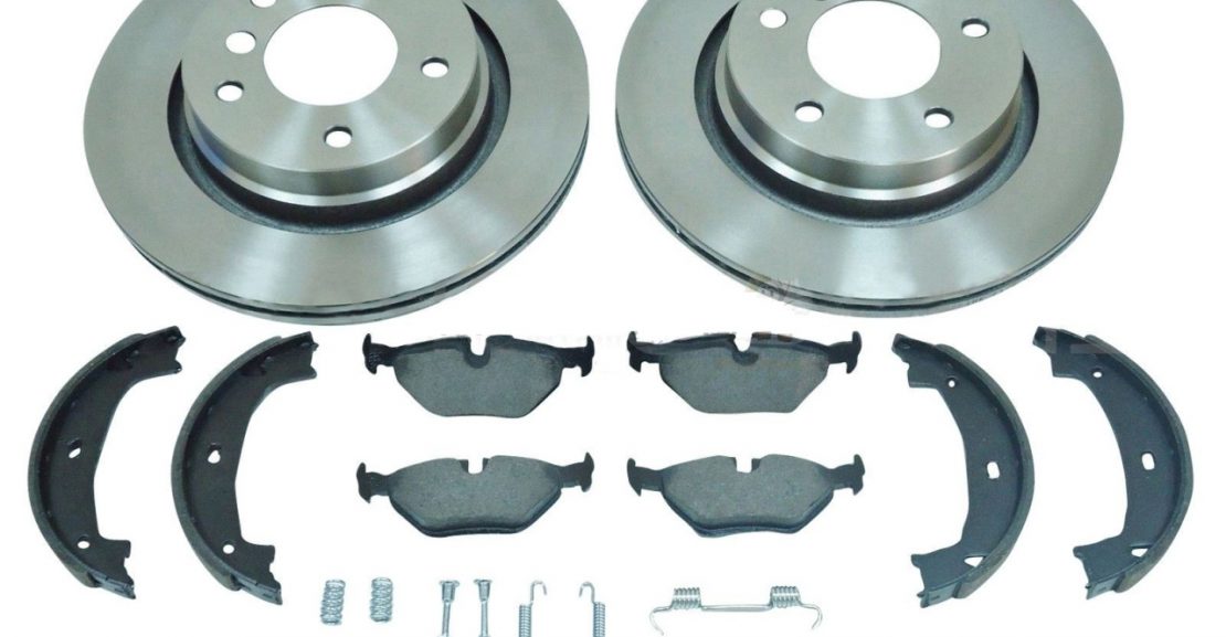
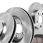
The following information shows the steps to change the rear brake pads and rotors on an E36 chassis.
Disclaimer: The following information details the steps which I used to perform this brake job on my car. If you do similar work on your car be expected to deal with problems that may arise which are not documented in these steps. Some of these problems may require tools which are not listed here or skills that you may not possess and almost always take longer to resolve than expected. Caution must be taken to properly secure your car when working underneath it to avoid injury (or death). Because of the critical nature of the braking system, injury or death may result to yourself or others if the brakes are not properly installed. If you are not comfortable performing these steps, seek help from a qualified person to assist you.
Preparation
Before starting the work shown here I measured the thickness of the rotors in advance and determined that they were very close to the minimum thickness and purchased replacement rotors in advance with the new pads. The minimum thickness for E36 rear rotors are as follows:
Solid: 8.4mm
Vented: 17.4mm
M3 Vented: 18.4mm
The rear rotors on our 328i Cabrio measured in at 17.44mm or .04mm left. Not that much and I figured that it was worthwhile replacing the rotors while I was in there replacing the pads.
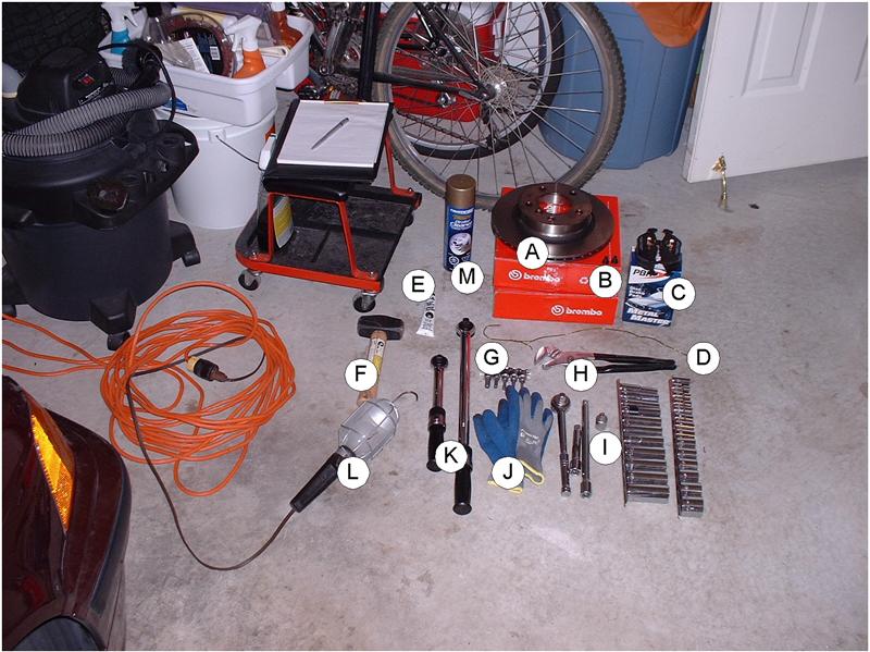
A) 2 new brake rotors
B) 2 new rotor mounting bolts
C) set of 4 brake pads
D) Wire coat hanger
E) Anti-squeal brake lubricant
F) Small sledge hammer
G) Hex sockets (6mm and 7mm)
H) Slotted pipe wrench
I) Socket set
J) Gloves
K) Torque wrenches (should span 16 Nm to 110 Nm)
L) Trouble light
M) Brake cleaner
Not shown: Degreasing product (I use Simple Green), rags, anti-seize compound, wire brush
Safety notice: Before changing the rear brakes, you must be prepared to jack up the rear of the car and place both sides of the car on jack stands as both wheels must be removed at the same time. In order for this to be done safely, you must be able to put blocks on the two front tires to prevent it from rolling as you must release the parking brake as well for this job.
The process of changing the brake pads or rotors exposes the brake materials which will release brake dust into the air. Brake dust is harmful and should not be inhaled. Work in a well ventilated area and take the necessary precautions to avoid inhaling brake dust.
Step 1: Block both front wheels securely.
Step 2: Jack up the rear of the car and put both sides on jack stands.
Step 3: Remove both wheels.
Step 4: Release the parking brake.
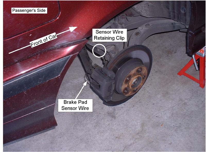
Step 5: Starting on the passenger side, remove the brake pad wear sensor cable from the retaining clip.
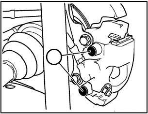
Step 6: Remove the plastic covers from the caliper guide bolts.
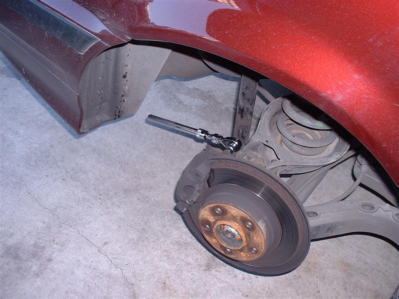
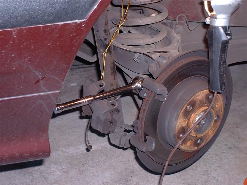
Step 7: Using the 7mm hex socket, loosen the upper and lower caliper guide bolts as far as they will go. On the rear brakes, the shock will make it difficult to access the caliper guide bolts so you must use a relatively slim ratchet.
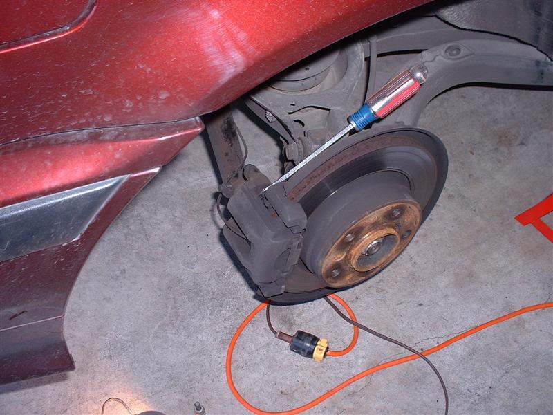
Step 8: Using a flat screwdriver, carefully push the caliper bolts through the rubber bushing so that it can be pulled out from behind.
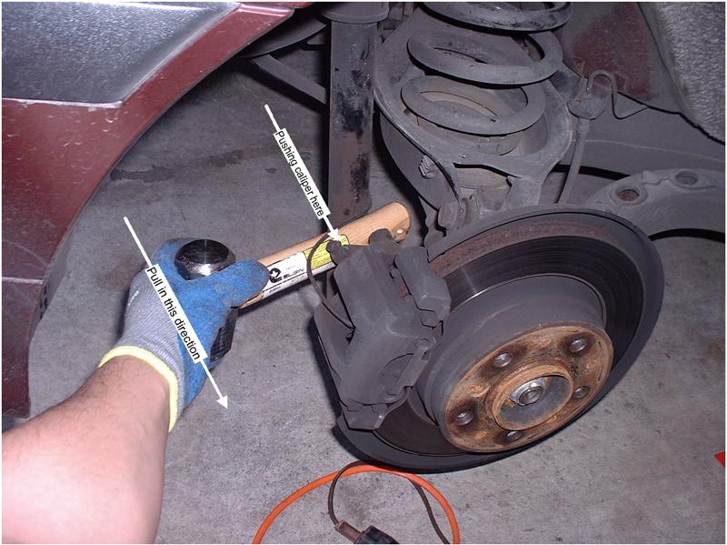
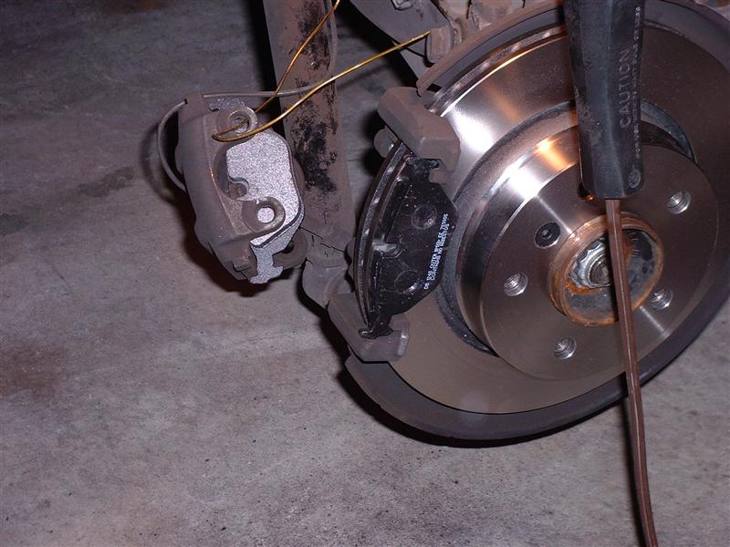
Step 9: As you will be installing brake pads that are likely much thicker than the ones in place, you will need to push the caliper piston back into the caliper so that the new pads will make it over the rotor. An easy way to do this is to use the wooden handle levered against the shock pulled towards you.
Caution: If your brake fluid reservoir (in the engine compartment) is full close to the top, pushing the piston back into the caliper as stated above may overflow the reservoir. As such, you may need to remove some of the brake fluid from the reservoir if it gets close to the top.
If this technique doesn’t push the piston far enough into the caliper, you can use the adjustable pipe wrench – placing a rag over top of the piston so that the rubber piston gasket is not damaged.
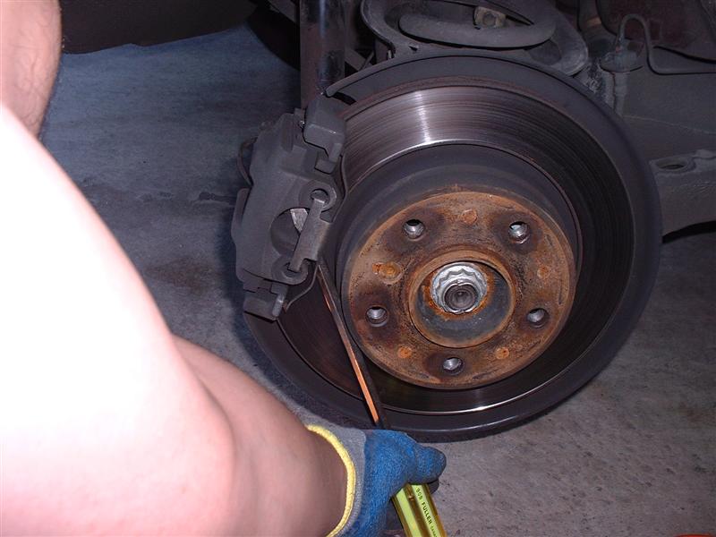
Step 10: Using a screwdriver, pop out the anti-rattle clip.
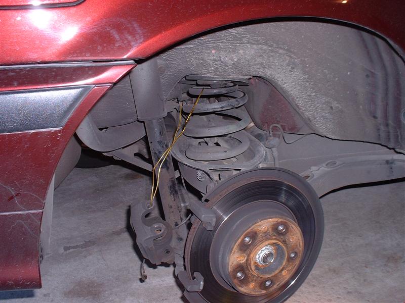
Step 11: Bend the hanger over one of the spring coils.
Step 12: Pull the caliper assembly out from the rotor. Hang the caliper on the other end of the wire hanger so that it does not hang free and strain the brake fluid hose.
Step 13: Carefully disconnect the wear sensor cable clip from the inner brake pad. A small metal clip attached to the end of the sensor cable may fly out when you remove the sensor – don’t lose this as you will need it when the sensor is reinstalled.
Step 14: Remove both the inner and outer brake pads.
Step 15: Using a 16mm socket, remove the two brake pad carrier mounting bolts then remove the carrier. These two bolts are torqued on quite tight so you may have to use a long breaker bar to remove them.
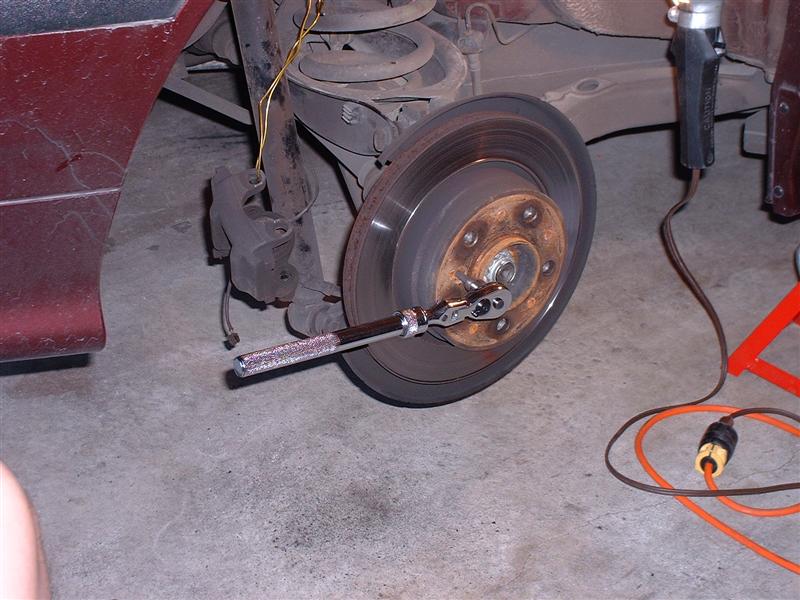
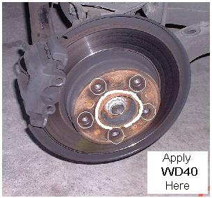
Step 16: The rotor is only held on by a single 6mm hex bolt. Remove this bolt using the hex socket. If the bolt is difficult to remove, apply some WD-40 or similar lubricant.
Step 17: Under normal circumstances, the rotor should be able to be removed out at this point. Sometimes the rotor may be seized on and will not budge. The first thing to do is try hitting the back of the rotor (towards you) to release it.
Note: Unless you are replacing the rotors, cover the rotor with a cloth to protect the surface and use a plastic or rubber mallet to strike it. If you are replacing the rotors, use the largest hammer that you can get your hands on.
Step 18: If the rotor still isn’t budging, apply some WD-40 and let it sit for about 10 minutes before retrying.
Step 19: Once the rotor is out, set it aside. If you are going to remount the existing rotors place them on a cloth to protect the surface.
Step 20: Clean the anti-rattle clip and both caliper guide bolts in degreaser then brake cleaner. Make sure that all residue is removed from the caliper guide bolts. Dry all parts.
Reinstallation
Step 21: Clean the rotors to be installed with a degreasing agent then follow with brake cleaner (both sides). Remove any residue with a clean cloth.
Step 22: Make sure to remove all traces of WD40 in the hub area if you used it.
Step 23: Clean the hub area with brake cleaner or with a wire brush.
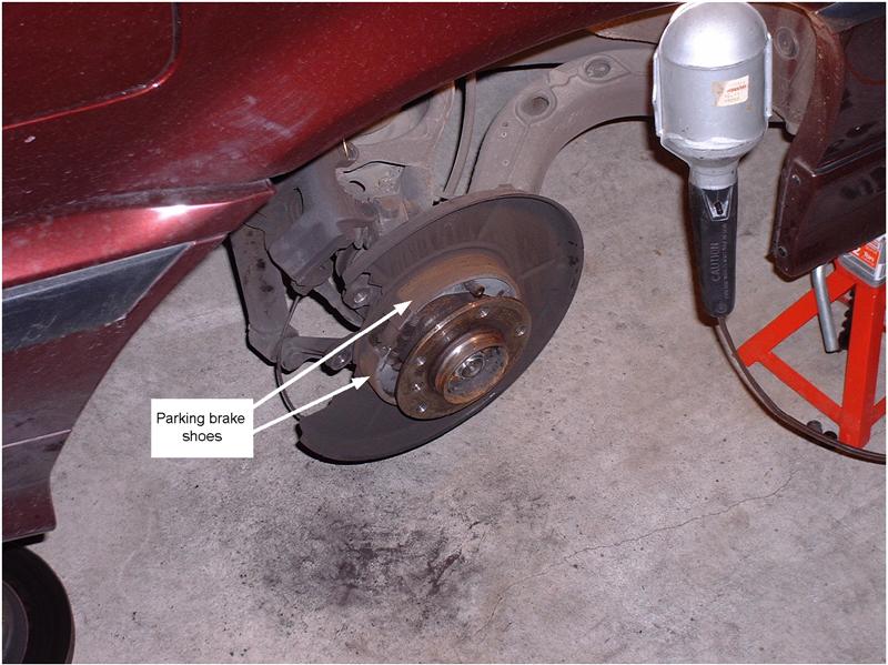
Step 24: Clean off the parking brake shoes with a rag to release as much of the brake dust residue.
Step 25: Brush some anti-seize compound onto the centre part of the rotor that will be in contact with the hub.
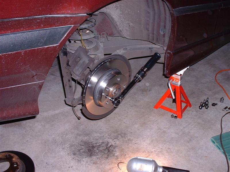
Step 26: Mount the new rotor onto the hub. Try to avoid touching the rotor surface with your (dirty) hands and only hold the rotor by the edges.
Step 27: Rotate the rotor on the hub until the mounting hole lines up.
Step 28: Insert a new mounting bolt and tighten to 16 Nm.
Step 29: Reengage the parking brake (inside the car). If the parking brake handle rises more that about 4-5 “clicks”, the parking brake shoes will have to be adjusted. If this is not required, proceed to step 30.
Parking Brake Adjustment
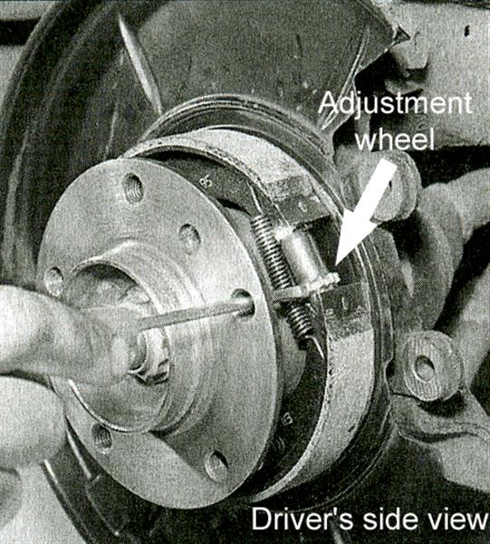
Step i: The parking brake adjuster resides in the parking brake assembly which is located inside of the rear rotors. The adjustment for the parking brake shoes is done from a small adjustment wheel that is accessible through one of the wheel bolt holes on the rotor.
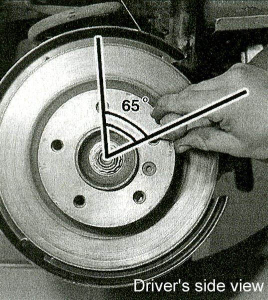
Step ii: Turn the rotor so that one of the wheel bolt holes is at 12:00. Using a light, you should be able to look into the bolt hole which is immediately down and to the rear of the car and see the adjustment wheel.
Step iii: Insert a flat screwdriver into the hole and spin the adjusting wheel as follows:
* On the passenger side of the car, spin the adjusting wheel downwards
* On the driver side of the car, spin the wheel upwards
Step iv: Continue spinning the adjusting wheel until it cannot be turned any more. At this stage, the parking brake adjustment for that wheel should be fully expanded and the rotor should not turn if you try to. If the rotor spins, the adjusting wheel is not expanded to its fullest position.
Step v: Turn the adjusting wheel in the opposite direction 4 times.
Step vi: Do the same procedure on the other wheel (noting the difference in directions from the opposite wheel). This assumes that you have similarly disassembled the brake on the other side of the car.
Step vii: When these steps are completed, both rotors should spin freely (as much as is normal) and the parking brake handle should only “click” about 4-5 times when lifted.
Step viii: Keep the parking brake engaged.
Reinstallation (continued)
Step 30: Reinstall the brake pad carrier. Tighten bolts to 67 Nm.
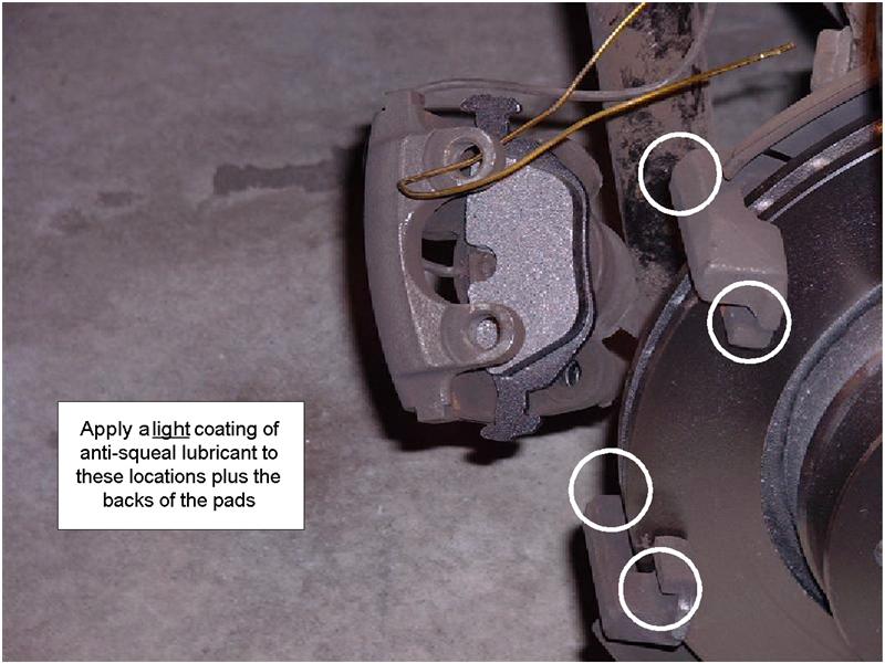
Step 31: Apply anti-squeal lubricant to the areas of the brake pad carrier where the pads will touch. Also apply this to the back of the new brake pads.
Caution: Under no circumstances should any foreign materials such as grease get onto the rotor surface. If necessary, remove any excess anti-squeal lubricant or clean the rotor with brake cleaner.
Step 32: Insert the clips of the inner brake pad into the caliper piston making sure not to touch the brake pad surface material.
Step 33: Insert the outer brake pad into the outer slot in the brake pad carrier.
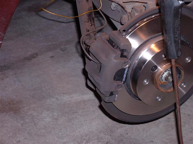
Step 34: Unclip the wire hanger from the caliper then move the caliper assembly into it’s original position and over top of both brake pads.
Step 35: Reinstall the upper and lower caliper guide bolts. Torque to 30 Nm.
Step 36: Reinstall the anti-rattle clip.
Step 37: Reinstall the plastic caliper bolts caps.
Step 38: Re-attach the brake wear sensor cable to the sensor cable clip.
Step 39: Perform the same procedure on the other side.
Step 40: Reinstall both wheels (torquing the lug bolts to 110 Nm).
Step 41: Remove the jack stands from both sides and return the car to the ground.
Step 42: Start the car and pump the brakes several times to ensure that the pads are seated properly.
Step 43: Take the care for a test drive and ensure that the brakes operate smoothly.
For the first few hundred kilometres, the brakes will seems somewhat less effective than usual – this is normal. During this break in period, avoid sudden, hard stops if possible. Normal braking performance will return after the break in period.
Step 44: Clean up your tools.

